Marine exposure and wind
The large VHF structure needed to tolerate coastal weather, accelerated corrosion conditions and high wind loads while remaining within the limits of a portable mast.

A communications equipment company had validated a new VHF radiator as a wire model. Zambeel turned it into a transportable, marine-ready antenna that a small field team could assemble, install, validate and reproduce.
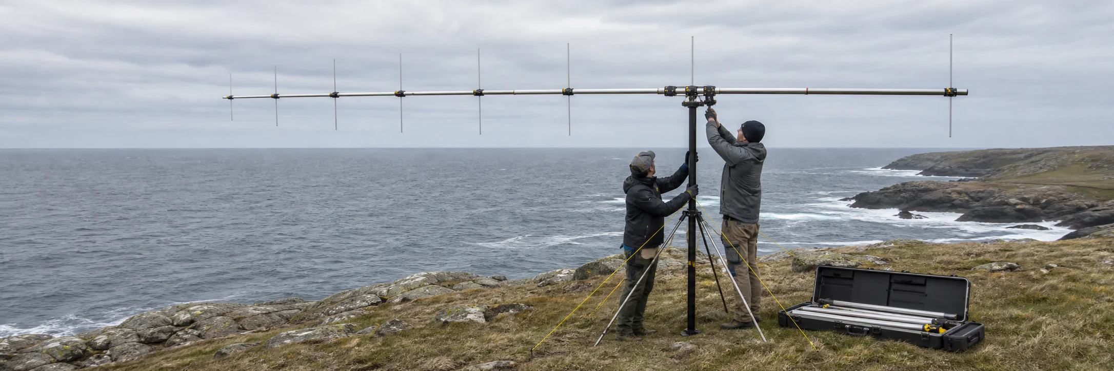
Zambeel turned a validated radiator into deployable field equipment and a documented manufacturing method the client could reproduce.
How engagements workThe requirement
The client’s RF team had designed the receiving antenna and tested a wire model. Zambeel was commissioned to resolve the mechanical architecture, materials, transport and installation requirements without compromising the validated radio-frequency behaviour.
The large VHF structure needed to tolerate coastal weather, accelerated corrosion conditions and high wind loads while remaining within the limits of a portable mast.
Some installation sites lacked proper road access. The complete antenna had to break down into manageable sections that could be transported and assembled without workshop equipment.
One person needed to assemble the antenna without tools. A second person would be required only to stabilise it during mounting onto the mast.
Development strategy
Zambeel divided the antenna into mechanical questions that could be resolved independently with representative loads, sample materials and partial assemblies. This reduced machining and material commitments while the design was still changing.
The boom-to-element connection was developed using placeholder versions of the smallest and largest elements with mock weights, verifying retention, repeatable alignment and tool-free engagement.
The central boom’s folding arrangement, section lengths and joining behaviour were resolved separately around transport volume, assembly sequence and final stiffness.
Candidate aluminium systems were evaluated through simulation and accelerated salt-exposure, corrosion and temperature testing before full quantities were ordered.
Mechanical architecture
Bespoke machined connections allowed the antenna to remain light, align consistently and assemble without loose specialist tooling. The detailed interface geometry and alloy selection remain confidential.
Custom-machined fittings located and retained each element while supporting fast, tool-free assembly by one person.
The long antenna structure divided into manageable sections without losing the alignment and stiffness required after deployment.
The mast interface and equipment distribution kept total weight and centre-of-mass behaviour within the portable support system’s limits.
Materials, finishes and interfaces were developed around salt exposure, outdoor temperature variation and repeated field handling.
Engineering validation
Mechanical changes could affect element position and therefore receiving performance. Zambeel’s engineers remained involved in the RF test programme while developing the structural operating envelope and material system.
Simulations examined the complete antenna under wind loading, informed the boom and element structures, and established a limits envelope for the mast interface.
Accelerated corrosion and salt-exposure tests were carried out through specialist university metallurgy facilities, alongside sample-level assessment of thermal behaviour.
Zambeel participated in receiving-performance tests with the client’s RF team, using measured results to check that the mechanical product retained the intended electrical behaviour.
Field iteration and handoff
After two development iterations, the complete antenna was taken into the field with the client. Installation and securing under coastal conditions exposed practical details that could not be resolved through analysis alone.
Field handling confirmed the assembly sequence and led to further refinements in how the antenna was secured for high-wind operation.
The final design combined the mechanical drawings, bespoke interfaces, assembly method, operating limits and manufacturing process developed through the programme.
With the prototype validated and the build method documented, the communications company produced subsequent units using its own manufacturing resources.
What changed
The final antenna met the mechanical needs of coastal deployment while retaining the receiving performance required by the client.
It could be transported in sections, assembled without tools by one person and mounted to the portable mast by a two-person field team.
The client did not remain dependent on Zambeel for serial supply: the validated design and manufacturing method allowed further units to be produced in-house.
Capabilities involved
The engagement combined design engineering, applied materials work, laboratory access, field validation and documentation for a client that already owned the core RF concept.
Architecture, transport breakdown, tool-free assembly, custom interfaces, folding mechanisms and mast integration.
ExploreWind-load simulation, weight distribution, stiffness, interface loads and portable-mast operating limits.
ExploreCandidate-material studies, accelerated salt exposure, corrosion testing and access to specialist research facilities.
ExploreUnit-level validation, complete prototype development, field refinement, drawings and repeatable production methods.
ExploreRelated work
We can help turn a validated technical concept into a transportable, testable and repeatable physical system.